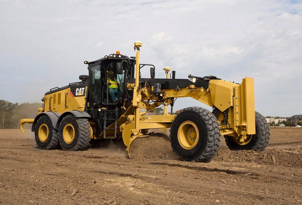

Before operation, the grader shall adjust the shovel angle, plane angle, inclination angle and side extension inclination of the blade through the cooperation action of the control lever according to the operation requirements, so as to meet the needs of different working conditions.

(1) adjustment of shovel angle
Shovel angle is the cutting angle, which refers to the angle between the blade and the ground. Generally, the angle of bulldozer has a certain adjustment range to adapt to different operation requirements. The medium cutting angle (about 60 °) is suitable for general flat operation. When cutting and stripping soil, such as stripping turf, scraping flange, cutting roadside ditch, etc., smaller shovel angle is required to reduce cutting resistance. When paving and mixing materials, a larger cutting angle should be selected, so as to avoid the pushing force of large materials on the blade, and it is easier for large particles to roll under the blade. Because of the large shovel angle, the load of the blade is reduced, so that the rolling mixing effect of materials is strengthened.
The shovel angle is within 40 ° of the adjustment range. The adjustment method is as follows:
Step 1: rotate the blade to make it perpendicular to the longitudinal axis, and then lower the blade to the ground.
Step 2: loosen the lock nut on the blade and remove it together with the stop plate.
Step 3: raise and lower the blade to change the angle of the blade. When the blade is raised, the blade angle increases, but decreases.
Step 4: tighten the lock nut after adjustment.
(2) adjustment of plane angle and inclination angle
The blade can rotate 360 ° under the drive of the pinion in the rotating worm gear box. The plane angle and inclination angle are changed by controlling the blade rotation or blade lifting according to the needs of the operation. When turning the blade, pay attention not to collide with the tire, gearbox, guard board and other parts, so as to avoid damaging the parts. The plane angle and inclination angle should be in accordance with the reasonable use range under various soil conditions.
(3) adjustment of blade left (right) side extension
Step 1: lower the shovel force to the ground.
Step 2: remove the blade moving hydraulic cylinder piston rod pivot seat, operate the blade side extension control lever to move the pivot seat to the left (right) side, and fix it firmly.
Step 3: raise the blade and operate the tongue hydraulic cylinder to move the tongue to the left (right).
Step 4: operate the blade side extension lever to extend the blade to the left (right).
(4) adjustment of blade right side extension tilt
Step 1: extend the blade to the right according to the method of blade side extension.
Step 2: pull out the locating pin of the ring frame.
Step 3: operate the traction frame to move the control lever, drive the circular frame to rotate, align the pin hole with the left pin hole of the guide frame, and insert the positioning pin.
Step 4: raise the blade to shorten the piston rod of the right hydraulic cylinder and extend the piston rod of the left hydraulic cylinder.
Step 5: operate the tractor to move the hydraulic cylinder so that the tractor continues to move to the right and move the blade to the right of the frame.
Step 6: operate the blade swing lever to make the blade stand up (for slope scraping).
(5) adjustment of scarifier
When the scarifier is required to work, the working position of the rake teeth can be changed by removing the spring pin and pulling out the rake teeth shaft. Put down the rake teeth and push the positioning rod back. If it is necessary to reduce the number of harrow teeth, a spacer shall be placed between the harrow teeth to prevent the harrow teeth from moving left and right. During scarifying operation, the hydraulic cylinder shall be raised and lowered by the blade so that the scarifier can get the appropriate depth of soil penetration, with the maximum depth of 150 mm. The adjustment method of scarifier is shown in Figure 2-33.
(6) adjustment of slewing clearance
After a long time of use, the fit clearance will increase due to wear. If the radial runout is found, and the clearance is more than 3mm, or the axial clearance is more than 2.5mm, it is necessary to adjust the rotary ring gear guide plate, as shown in figure 2-34.
① adjustment of axial clearance. Screw out the nut, take down 4 guide plates, increase or decrease the adjusting gasket to adjust the axial clearance, and ensure that the normal clearance is 1mm. After the clearance is adjusted, reinstall the guide plate.
② adjustment of radial clearance. Loosen the fixing nut and lock nut, and screw the adjusting nut to adjust the radial clearance of guide plate to 0.5mm. After adjustment, tighten all nuts, and the tightening torque of nuts is 590n · M.
CONTACT US
PRODUCT CENTER
QR CODE
